Lab 1: FPGA and MCU Setup and Testing
Introduction
This lab built the foundation for all of the future labs in this class by pushing me to familiarize myself with all of the hardware and software components we will be using throughout the semester. First, I soldered all of the components for my board, putting together a network of switches, buttons, LEDs, and wiring to interface with MCU and FPGA development boards. Then, I wrote in Verilog to program and test a 7-segment display to get familiar with Radiant and Segger, the software tools that we will be using going forward. See the E155 Lab 1 Page for a more detailed overview of the specifications and instructions for this lab.
All code written for this lab can be found on my E155 Lab 1 Repository on Github.
Setup and Circuitry
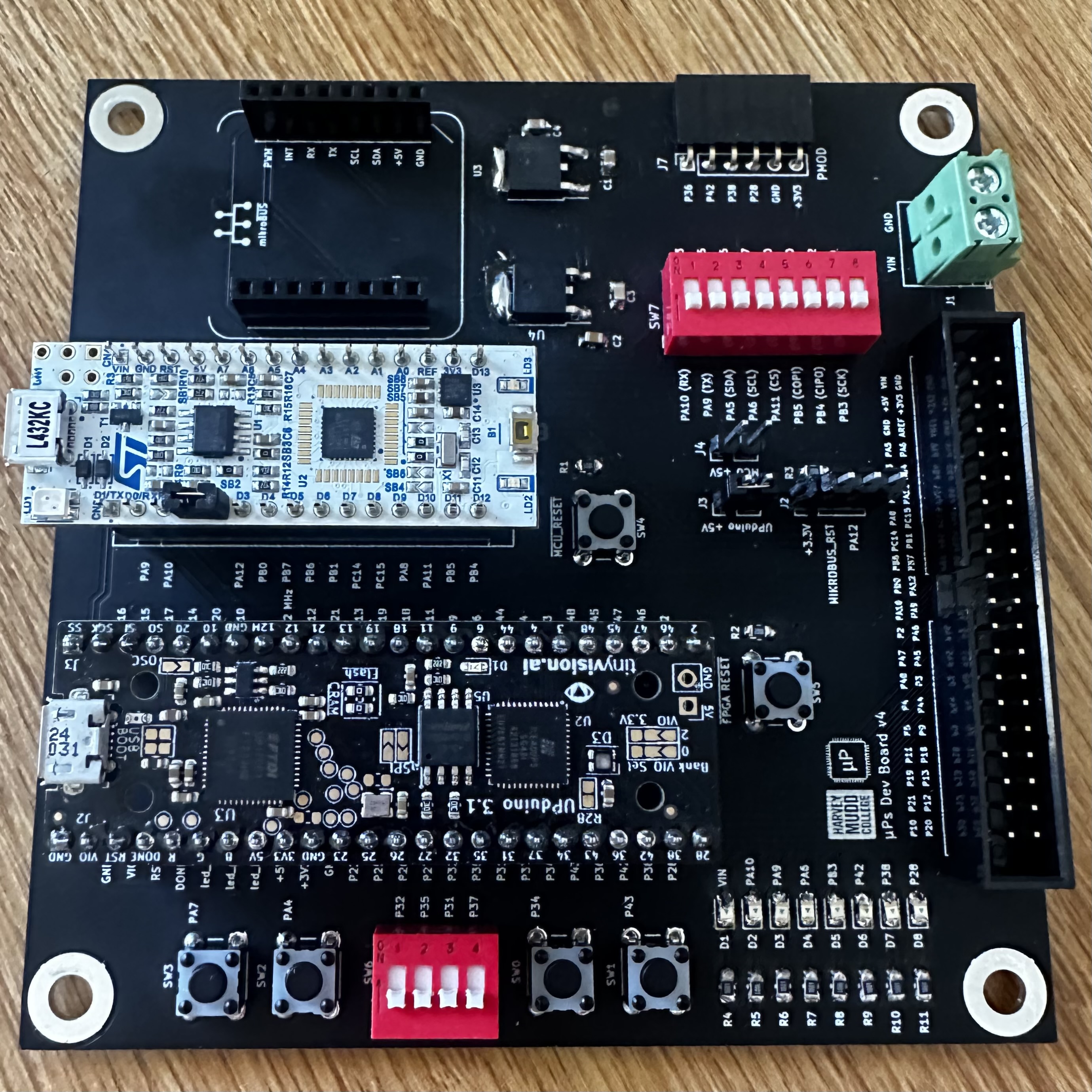 A picture of my completed board!
On the left is a picture of my completed board. It took around 4 hours in total to solder, including a breadboard connecter that is depicted
in the bottom left image of my circuit.
A picture of my completed board!
On the left is a picture of my completed board. It took around 4 hours in total to solder, including a breadboard connecter that is depicted
in the bottom left image of my circuit.
In order to setup the circuit for the 7 segment display, shown in the bottom left image, it was important to look at the datasheet to determine its specifications.
For the MAN6400 Series, the absolute maximum rating for continuous forward current is 30mA per segment. I chose an operating current of 10mA to stay well
below the maximum rating and found the appropriate resistor from V = IR. Given an input voltage of 3.3V, the resistor value needed to maintain
current at 10mA is 330Ω. Therefore, I connected a 330Ω between each segment and corresponding pin.
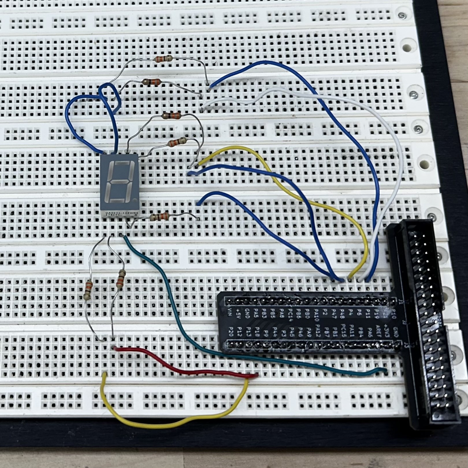 A picture of the final circuit implemented on a Proto-Board.
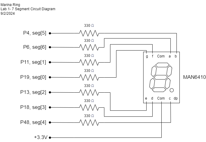 A circuit schematic for this lab.
The circuit schematic on the left details the Upduino pins I used to power the display. Since the MAN6410 is a common anode display, 3.3V is supplied at the
anode and each pin acts as a cathode. To turn a segment on, a pin is set to low or 0 and so current can flow down that path. To turn a segment off, the pin is
set back to high or 1. For controlling LEDs, I used onboard LEDs connected to P42 (led[0]), P38 (led[1]), and P28 (led[3]).
A circuit schematic for this lab.
The circuit schematic on the left details the Upduino pins I used to power the display. Since the MAN6410 is a common anode display, 3.3V is supplied at the
anode and each pin acts as a cathode. To turn a segment on, a pin is set to low or 0 and so current can flow down that path. To turn a segment off, the pin is
set back to high or 1. For controlling LEDs, I used onboard LEDs connected to P42 (led[0]), P38 (led[1]), and P28 (led[3]).
One specification for this project was to blink an LED at 2.4 Hz. I used the onboard High Speed Oscillator to generate a 24 MHz signal and a counter to do this. I then encoded a digitally controlled oscillator, or an N-bit counter that adds p on each cycle. Values for p and N can be determined through the formula f_LED = f_clk * p/2^N. For my system, I chose N = 32 and p = 430, which theoretically should produce a frequency of 2.403 Hz (an error of 0.12%).
Software and Verification
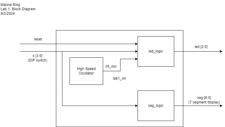 A block diagram model for this system.
On the left is a block diagram visualizing the Verilog modules that I used in this lab and their inputs, outputs, and connections. I separated the combinational logic
for controlling the LEDs and for controlling the 7 segment display in order to better be able to test their functions individually. By modularizing into these two blocks,
I was able to isolate errors within each block of combinational logic.
A block diagram model for this system.
On the left is a block diagram visualizing the Verilog modules that I used in this lab and their inputs, outputs, and connections. I separated the combinational logic
for controlling the LEDs and for controlling the 7 segment display in order to better be able to test their functions individually. By modularizing into these two blocks,
I was able to isolate errors within each block of combinational logic.
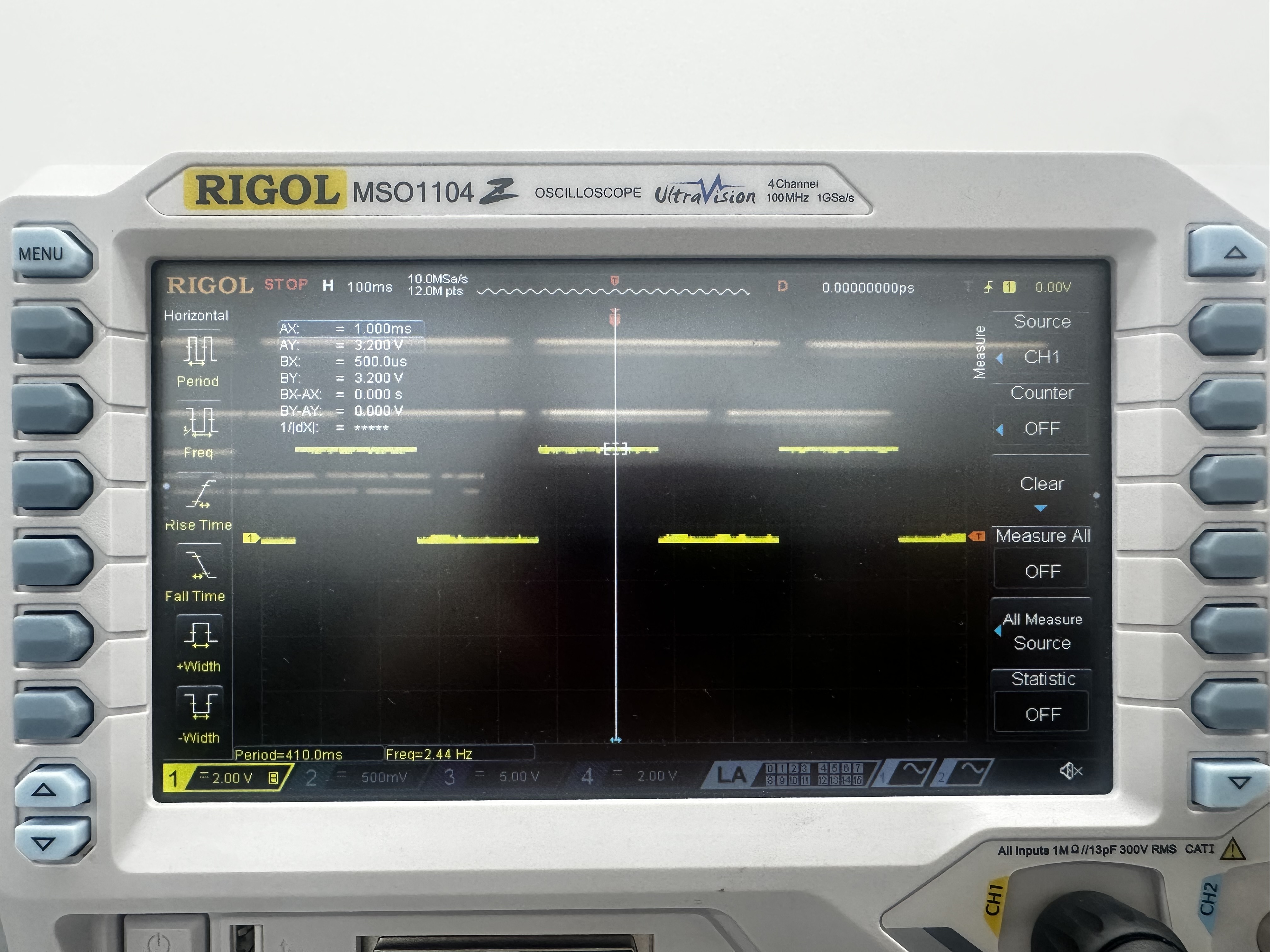 A photo of the oscilloscope measuring the blinking LED signal. Note in the bottom left corner, a frequency measurement of 2.44 Hz!
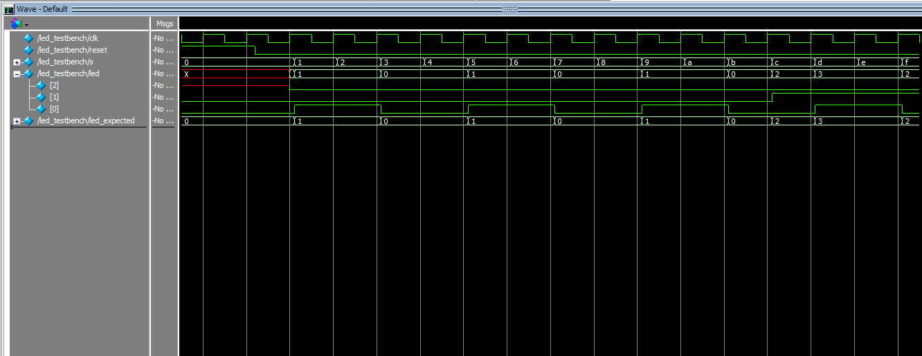
I wrote a testbench for each module with corresponding test vectors. For the led_logic module, the test vectors corresponded to each entry in the truth table shown here
Additionally, I also used an oscilliscope to verify the frequency of the blinking LED. As you can see in the photo on the left, I successfully produced a signal of approximately 2.4 Hz. The oscilliscope output is shown to the right and the successful ModelSim simulation result is shown below.
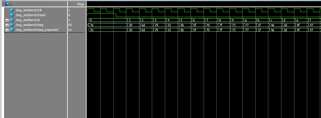
For the seg_logic module, the test vectors corresponded to each possible DIP switch input or all 4 digit binary numbers. The successful ModelSim simulation is shown in the last image below.
A photo of the oscilloscope measuring the blinking LED signal. Note in the bottom left corner, a frequency measurement of 2.44 Hz!
I wrote a testbench for each module with corresponding test vectors. For the led_logic module, the test vectors corresponded to each entry in the truth table shown here
Additionally, I also used an oscilliscope to verify the frequency of the blinking LED. As you can see in the photo on the left, I successfully produced a signal of approximately 2.4 Hz. The oscilliscope output is shown to the right and the successful ModelSim simulation result is shown below.
For the seg_logic module, the test vectors corresponded to each possible DIP switch input or all 4 digit binary numbers. The successful ModelSim simulation is shown in the last image below.
 The ModelSim waveform output of the seg_logic testbench
 The ModelSim waveform output of the seg_logic testbench
After testing, I successfully compiled and uploaded the Verilog modules to the Upduino. The design meets all of the requirements.
This lab took me 19 hours in total.